What Is The Difference Between Armature And Commutator?
If you strip a brushed DC machine down to the few parts that actually decide whether it works or just smokes, the armature and the commutator sit right at the center. The armature is where energy conversion happens in the magnetic field. The commutator is the rough mechanical trick that keeps the math pretending everything is DC. Same shaft, very different jobs.
Table of Contents
A quick mental model
Think of the armature as the region of the machine that interacts with flux and carries conductors, while the commutator is only the interface that periodically swaps which conductors you are talking to. The armature gives you induced EMF and torque. The commutator gives you a one-direction terminal voltage and usable brush currents by chopping and rearranging that mess.
Most datasheets blur this by casually saying “armature” when they really mean “rotor” assembly: core, slots, windings, shaft, and yes, the commutator sitting on one end. Strictly speaking, the commutator is geometrically attached to the armature but conceptually separate.
Where each one sits in the energy path
If you already know the textbook story, you know the chain:
Mechanical shaft power → armature conductors moving in field → alternating EMF induced in coils → commutator and brushes → DC at the terminals or DC in the windings, depending on generator or motor.
The armature lives in the second step of that sentence. It is the rotating iron stack and its embedded conductors, cutting flux and producing (or consuming) electrical power. The commutator lives at the fourth step. It does not make power. It edits the way individual coil voltages and currents connect to the outside world so the external circuit sees nearly steady polarity.
So the difference is not “one is mechanical, one is electrical.” Both are electro-mechanical. The difference is that the armature participates directly in electromagnetic induction, while the commutator only participates in routing and timing.
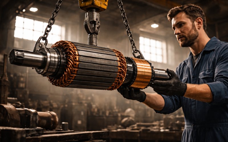
Physical construction: same shaft, different logic
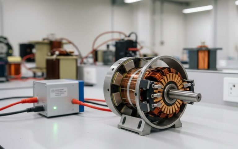
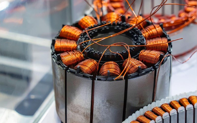
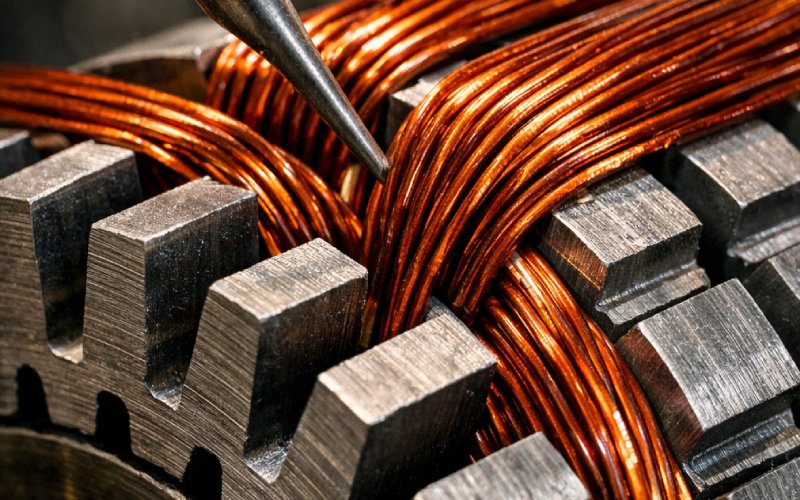
In most DC machines the armature is the entire rotating magnetic structure. It includes a laminated iron core keyed or clamped to the shaft, slots in the periphery, and the armature winding placed in those slots. The laminations are thin, insulated sheets to limit eddy losses.
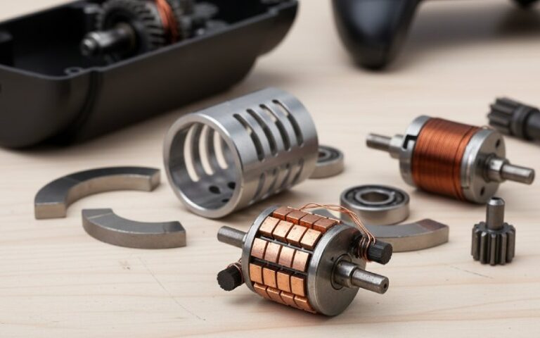
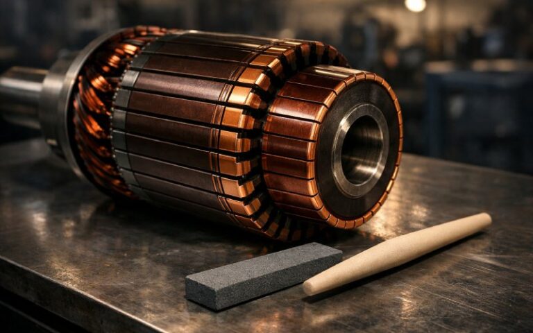
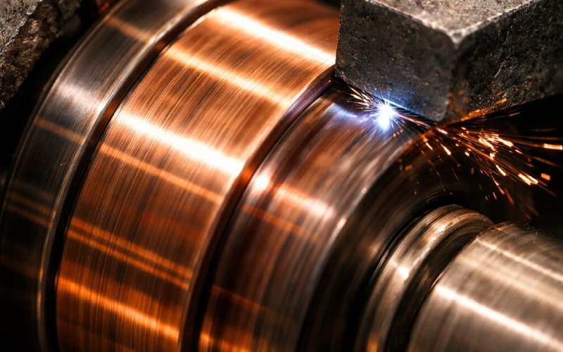
The commutator, by contrast, is a segmented copper cylinder on the same shaft, usually at one end of the armature. It is made of wedge-shaped copper bars, separated from each other and from the shaft by mica or similar insulation, with each segment tied to one end (or pair of ends) of an armature coil.
You can remove a commutator from a rotor and still recognize the remaining piece as “an armature core with windings.” Remove the core and coils but keep the commutator and shaft, and what you have is just a switching drum with nothing to switch for.
Armature vs commutator at a glance
Here is a compact comparison, keeping it practical rather than exam-style:
| Aspect | Armature | Commutator |
| Core purpose | It sits in the magnetic field and carries conductors so that EMF and torque are produced. | It periodically reverses or reconnects coil currents so that the external circuit or armature windings see a mainly one-way current. |
| Location | It occupies the main body of the rotor, running under the poles across the air gap. | It sits on the same shaft, usually at one end of the armature, facing the brushes. |
| What it is made of | It is typically a stack of silicon-steel laminations with copper windings laid in slots. | It is typically a ring of copper segments insulated by mica or similar material and clamped to the shaft. |
| Direct role in equations | It appears directly in E = kΦω and T = kΦIₐ through flux linkage and current in its conductors. | It is invisible in those equations; it only makes the underlying assumptions about current direction and commutation valid. |
| Type of quantity it handles | It handles distributed EMF and current in space; values vary coil to coil around the periphery. | It handles terminal-level collector currents and voltages at individual copper segments. |
| Typical failure signature | It tends to fail through insulation breakdown, hot spots, turn-to-turn shorts, or open coils in the slots. | It tends to fail through bar wear, flats, high mica, burning, tracking, or severe brush sparking at certain bar positions. |
| Replace vs rewind | It is usually rewound or replaced as an entire rotor assembly when heavily damaged. | It is often undercut, resurfaced, or in large machines even rebuilt segment by segment. |
| Interaction with brushes | The brushes only touch it indirectly through the commutator; flux reacts with armature current to cause armature reaction. | The brushes press directly on it and define the commutation zone and current direction in each coil as it passes. |
Design effort: where the real engineering goes
When you design or select a DC machine, you do not treat armature and commutator with the same thinking.
Armature design is about electromagnetic performance. You worry about slot geometry, tooth flux density, lamination material, winding layout, coil pitch, and how badly armature reaction will distort the main field under load. Those choices drive copper loss, iron loss, saturation, transient response, and noise. They also decide how many coils you have to wire into the commutator at all.
Commutator design is about commutation quality under the worst combination of current, speed, and environment. Here you care about segment count, segment width versus brush width, mica undercut depth, surface finish, run-out, and how brush material and spring pressure behave over time. The goal is simple on paper: keep the current transfer between segments smooth enough that arcs stay tame and bars do not erode faster than the business model can tolerate.
So the difference, again, is focus. The armature is sized for magnetic and thermal limits; the commutator is sized for switching stress and sliding contact.
How the difference shows up in math without being obvious
In the standard DC machine model, the armature shows up everywhere. The induced EMF is often written as:
Eₐ = kΦω
and the torque as:
T = kΦIₐ
where Φ is the air-gap flux, ω is mechanical speed, and Iₐ is armature current. Every term there is tied back to what armature conductors are doing in the field.
The commutator is not explicit in those equations. It hides in the assumption that each armature coil has its current reversed right around the point where the coil axis crosses the neutral plane, so that the net torque remains in one direction and the external terminals see unidirectional voltage.
If commutation is poor, you still write the same equations, but now you sprinkle in extra bits: commutation reactance, stray inductance, sparking, effective resistance increase. So the commutator’s “difference” is that it lives in the edge cases of the model rather than the core equations.
Failure modes: who complains first, armature or commutator?
On a tired machine, the commutator often complains earliest in a way humans notice. Visible arcing, bar discoloration, irregular brush marks, sharp smell. That is usually a commutator or brush issue, even if the root cause lies in armature design or overload.
Armature failures are less visible until they are very visible. Local hot spots, unequal bar voltages on a growler test, insulation degradation in the slots, or odd vibration because one part of the rotor has baked more than the rest. By the time copper has gone molten, the commutator is innocent and guilty at the same time: it only switched currents that the armature and the user insisted on supplying.
Here the difference matters practically. If you see progressive bar wear but coil resistances are still matched, you tend to treat the commutator and brushes. If you see segment-to-segment voltage irregularities or repeated flashovers at the same mechanical position, you start suspecting a particular armature coil group, not just surface finish.
Manufacturing and maintenance viewpoints
From a factory perspective, building an armature is mainly a lamination, stacking, slot insulation, winding, and impregnation process. Alignment to the shaft and balance are critical, but the main risks are insulation defects, copper placement, and incomplete impregnation.
Building a commutator is a machining and assembly process. The segments must be clamped, insulated, pressed, turned to a precise cylinder, undercut, and sometimes dynamically checked for bar movement under temperature. It is quite a different skill set.
On the shop floor during maintenance, the armature is inspected with electrical tests and thermal history in mind. You look for shorts, opens, grounds, loosened coils. The commutator gets mostly visual and mechanical attention first: run-out checks, mica depth, surface roughness, brush track, and sparking behavior under load.
So the difference in daily life is simple: armatures are tested, commutators are “looked at and listened to,” and both end up blamed depending on who is holding the meter.
Common misconceptions, cleaned up briefly
One common confusion is using “armature” and “rotor” as perfect synonyms. In many DC machine designs, the armature winding is on the rotor and the terms accidentally line up. In others, such as some AC machines and certain specialized DC topologies, the armature can be on the stator. The commutator does not move in those designs because there is no commutator at all; electronic switching takes its place.
Another misunderstanding is thinking the commutator “creates DC.” It does not magically straighten anything; it just rearranges coil connections so that what was already an alternating distribution of coil voltages around the periphery appears as a roughly constant-polarity output at the brushes. The armature is where that alternating EMF originates.
A quieter misconception is that a larger commutator always implies more power. Often it only implies more segments, which can be driven by a desire for smoother commutation at a given power level, or by voltage and speed constraints, not just rating.
Short wrap-up
So the difference between armature and commutator is not subtle once you look at what each one actually “owns.” The armature owns flux interaction, EMF, and torque. The commutator owns current direction, segment switching, and brush contact. One sits inside the field and makes the physics happen; the other sits at the end of the shaft and makes the physics usable as DC. Everything else is just naming habits and catalog shortcuts.