Types of AC Commutator Motors
AC commutator motors sit in a narrow niche now: high starting torque, wide speed range, compact frames, and constant negotiation with brush wear and commutation limits. They are no longer the default industrial drive, but if you work with legacy plants, appliances, or special-purpose machinery, you still need to know which type is actually in front of you and what that implies for control, power quality, and maintenance.
Table of Contents
What engineers mean by “AC commutator motor”
The term covers machines that run from an AC supply yet use a segmented commutator and brushes to manage rotor current. In other words, they borrow the mechanical switching of DC machines but accept sinusoidal supply. Textbooks normally group them separately from induction and synchronous motors because the torque–speed curves, power factor behaviour, and maintenance profile are quite different.
Two broad families exist. Single-phase types evolved directly from DC series motors: AC series, compensated series, universal, and the repulsion variants. Polyphase commutator motors, mainly the Schrage and its relatives, use injected rotor EMF to obtain smooth variable speed while still synchronising with a three-phase grid.
You already know how the windings are connected and how commutation works. The interesting part now is how the variants differ in practice: torque behaviour, control options, typical power levels, and what to do with them in a plant that also has VFD-fed induction machines and modern drives.
Big picture classification
Most modern notes on AC machines list these commutator types: series, compensated series, shunt, repulsion, repulsion-induction, repulsion-start induction-run, plus polyphase designs such as the Schrage motor.
The table below gives a compact orientation before we walk through each group. The numbers are only indicative but good enough for design-level thinking.
| Family | Representative types | Supply | Main speed control handle | Typical starting torque vs rated | Where you still see it |
|---|---|---|---|---|---|
| Series family | AC series, compensated series, universal | Single-phase (universal can also use DC) | Voltage control, phase-angle control, simple choppers on DC | Around 2–3× rated torque, sometimes more in small tools | Hand tools, mixers, domestic appliances, small drives under a kilowatt |
| Repulsion family | Repulsion, compensated repulsion, repulsion-start induction-run, repulsion-induction | Single-phase | Brush angle, transition to cage operation, tap changing | Often 3–4× rated torque, very strong at zero speed | Older compressors, machine tools, hoists, some traction and lift gear |
| Shunt AC commutator | Shunt, fixed-brush shunt-characteristic motors | Single-phase or three-phase | Field voltage control, brush position (less range than Schrage) | Moderate, similar to DC shunt behaviour | Legacy constant-speed industrial drives, often now retrofitted |
| Three-phase commutator | Schrage, rotor-fed variable-brush motors, stator-fed fixed-brush motors | Three-phase | Injected EMF magnitude and phase via commutator, brush shift | High, close to constant torque across range | Textile machines, printing lines, rolling mills installed before VFD era |
With that map in your head, the variants stop looking like a long list and start to form two or three families that behave in recognisably different ways.
Series family: AC series and compensated series motors
A plain AC series motor is essentially a DC series motor adapted just enough to survive on alternating current. Reactance of the field limits current, and the armature looks like a transformer secondary with a shorted turn at standstill, which stresses the commutator. That is why serious textbooks repeatedly say that uncompensated AC series motors are practical only in very small ratings.
The compensated series motor fixes that by adding a compensating winding in the stator, in series with the armature, positioned so that its magnetomotive force cancels the armature reaction under the poles. This does three things at once. First, it improves commutation at low speed and at high load. Second, it allows a smaller air gap and fewer field turns, which reduces reactive voltage drop and improves power factor. Third, it makes the torque–speed curve look more like a DC series motor over a meaningful operating range, rather than collapsing as soon as the load changes.
Design wise, once you include the compensating winding, the machine becomes the “default” AC commutator motor. Most historic AC series drives of any size are actually compensated series machines even if the nameplate is vague. The lack of precision in naming causes trouble when someone specifies replacement brush grades or rewinding data from an old drawing that only says “AC series”.
From a modern control perspective, the series family is easy to modulate using very simple electronics. A phase-angle controller or triac dimmer can vary speed in a crude but workable manner. No feedback, just power slicing. The cost is noise, both acoustic and electromagnetic, and a power factor that can be quite poor at light load. That trade-off is acceptable in a drill or blender where duty is intermittent and the grid is stiff. It is much less acceptable when the motor is tens of kilowatts inside a plant that already struggles with harmonic compliance.
Universal motors: same frame, AC or DC
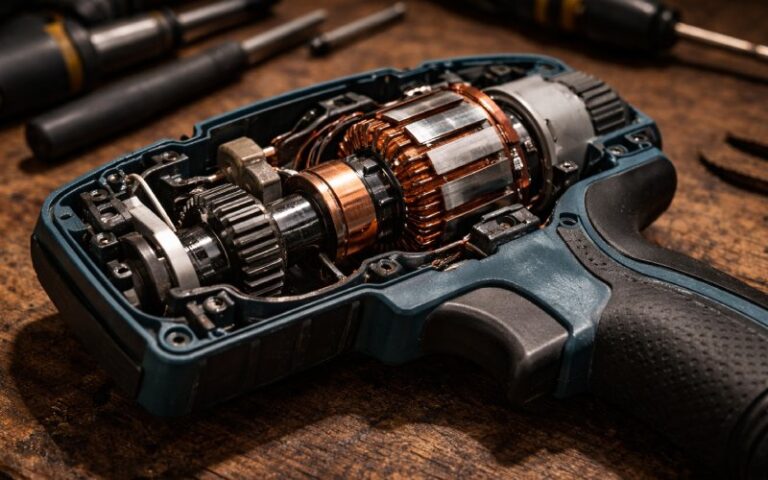
Universal motors are simply compensated series motors built small enough that iron losses and commutation limits remain tolerable across both AC and DC. Their signature is speed capability: tens of thousands of revolutions per minute from a very compact frame, on either supply type.
The torque–current relationship is almost identical on AC and DC because the same series field is used. On AC, the winding inductance and iron losses reduce speed somewhat, but saturation at the peaks of the sine wave pushes it back up; the net effect is a speed that does not change much between DC and 50/60 Hz.
In practice, universal motors are the only AC commutator motors most non-specialist engineers see today. They appear in vacuum cleaners, grinders, jigsaws, hair dryers, and many other devices where you want aggressive power in a small, cheap package and you can accept brushes, noise, and finite life. When one fails, you replace the appliance, not just the motor. That business reality drove the mechanical design as much as electromagnetic considerations.
From a system design viewpoint, universal motors interact strongly with supply impedance. Voltage sag under starting or stall can be significant on weak networks, so you sometimes see them paired with soft-start circuits or simple current limiting. Control via phase-angle dimming is so common that engineers sometimes forget the underlying machine is still a fully wound commutator motor with all the usual brush and commutation sensitivities.
Repulsion family: when you really need starting torque
Plain repulsion motors place a single-phase field on the stator, directly connected to the AC line, and a wound rotor linked to a commutator with short-circuited brushes set at an angle to the field axis. The stator induces current into the rotor windings; the angled brush axis lets the rotor field oppose and shift relative to the stator field, producing torque.
The interesting aspect is that you get transformer-like behaviour at standstill without drawing enormous starting current from the supply. Starting torque can easily exceed several times rated torque while current remains manageable. That made repulsion motors attractive for lifts, early traction, and heavy-duty drives where DOL starting of an induction motor would have required absurdly low impedances or large autotransformers.
Speed control in a plain repulsion motor comes from shifting the brushes mechanically. Move them towards alignment with the field and torque drops; move them away and torque reverses. This kind of mechanical control is smooth but labour-intensive. It is fine when a drive runs at a few fixed speeds set by maintenance staff, but not when you want closed-loop regulators and recipes with hundreds of setpoints.
Compensated repulsion motors add a series compensating winding, similar in idea to the compensated series motor. The goal again is better commutation and power factor, but here it also shapes the torque–speed characteristic to look more like a series motor while retaining repulsion starting behaviour. Some texts refer to Latour-Winter-Eichberg designs with multiple brush sets and transformer taps feeding part of the commutator; these are clever but mechanically intricate machines, interesting in the lab and awkward in production.
Repulsion-start induction-run
Repulsion-start induction-run motors are a pragmatic compromise between repulsion and induction behaviour. At standstill, the rotor is a repulsion rotor with brushes and commutator, giving strong starting torque and decent power factor. At a speed close to running speed, a centrifugal device shorts all commutator segments together and often lifts the brushes, turning the rotor into something close to a squirrel cage.
From that point on, the machine behaves like a standard single-phase induction motor. This means that in steady state you get familiar characteristics, simple protection, and no continuous brush wear. The price is extra mechanical complexity in the change-over mechanism and commutator, plus the cost of the more intricate rotor.
Where do you still meet them? Mostly in older compressors, pumps, and heavy domestic or small industrial plant where high starting torque was essential but the designer still wanted simple induction-type running once the inertial load was moving. When such a machine fails today, you will often see it replaced by a capacitor-start induction motor plus a soft starter or VFD, because that combination is easier to source and maintain.
Repulsion-induction motors
Repulsion-induction motors combine a repulsion rotor winding connected to a commutator with an embedded squirrel-cage winding. At start, the repulsion action dominates, giving high torque with controlled current. As speed builds, the induced currents in the cage become more important and the behaviour drifts towards that of an induction motor, even without mechanically shorting the commutator.
This mixed behaviour gives an attractive torque curve for some applications but complicates the rotor design, insulation, and cooling. With the arrival of capacitor-start and capacitor-run induction motors, which give good starting torque without brushes and with much simpler construction, repulsion-induction types largely disappeared from new designs.
Shunt AC commutator motors
Classification charts sometimes include “shunt AC commutator motors” or “fixed-brush shunt-characteristic AC motors”. Conceptually, these are AC versions of DC shunt motors: the field is excited from the same supply but not in series with the armature. The result is a speed that is comparatively stiff with respect to load, closer to a constant-speed drive than a series machine.
Field control through a separate rheostat or transformer provides modest speed trimming above base speed by weakening the field. On AC, the advantage is less dramatic than in DC machines because of power factor and commutation constraints. That is one reason the class stayed small and specialised.
In practice you mostly encounter these in older plant where a constant-speed AC commutator motor drove a line shaft or critical machine before induction motors became cheap and widely controllable. If you inherit one, treat it as a high-maintenance constant-speed drive with limited parts availability; replacing it with an induction motor and VFD is usually simpler unless the mechanical integration is very tight.
Three-phase AC commutator motors: the Schrage and relatives
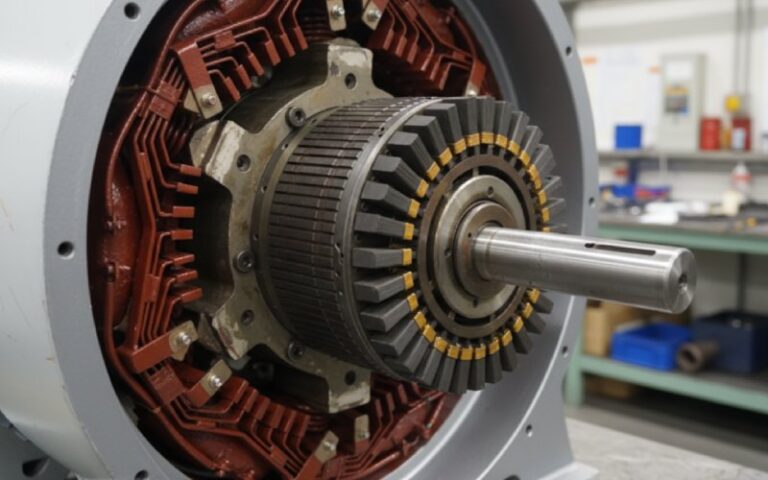
The Schrage motor is the most widely documented three-phase AC commutator motor. It is essentially a variable-speed induction motor in which an auxiliary three-phase EMF is injected into the rotor circuit via a commutator and adjustable brushes.
A typical Schrage has a three-phase stator, a rotor with a winding brought out to slip rings for the main supply, and a second rotor winding connected to a commutator. Adjustable brushes feed that commutator from a regulating winding. By shifting the brushes, you change the magnitude and phase of the injected EMF, which changes both slip and power factor. With suitable design you can run sub-synchronous, synchronous, and super-synchronous speeds from the same grid frequency while maintaining good torque and near-unity power factor over much of the range.
Before electronic drives, that combination was extremely attractive for textile machinery, rolling mills, and printing presses. You could obtain smooth speed variation, high efficiency, and reasonable control of reactive power without any rotating converters or mercury-arc equipment. The price was a mechanically complex rotor and commutator system that demanded skilled maintenance. Operators needed to understand brush setting, neutral adjustment, and the effect of contact condition on power factor.
There are also stator-fed AC commutator motors where the stator is supplied directly and the rotor commutator is used primarily for power factor control or speed trimming rather than wide-range variation. These are less common and often appear in older marine or traction installations. The general idea is the same: injected EMF via a commutator to manipulate slip and reactive power without changing supply frequency.
In modern designs, a standard induction motor plus a voltage-source inverter solves the same problem with fewer moving parts. So the Schrage and its cousins are now specialty subjects: you study them to understand historical drives or to keep a legacy plant running.
Choosing between types in real projects
In an all-new design today, almost nobody specifies a large AC commutator motor. That is not because the machines are ineffective; it is because power electronics make brushless options easier to justify. The real use case now is either replacement of a failed motor in existing equipment or incremental modernisation where you cannot justify a full mechanical redesign.
When you face a small appliance or hand tool, the choice is almost predetermined. Universal motors persist because they are cheap, compact, and easy to source from multiple vendors. If noise, EMI, or brush life becomes a serious issue, you shift the entire design to a brushless DC or permanent-magnet synchronous motor and accept the cost of the driver electronics.
For legacy single-phase industrial drives that still need high starting torque, you often find repulsion-start induction-run or repulsion-induction machines on the nameplate. In replacement, there are three common paths. One is a high-torque capacitor-start induction motor with a heavy-duty contactor or soft starter. Another is a three-phase induction motor with a small VFD fed from the single-phase supply. The third, less popular, is a like-for-like commutator motor sourced from a specialist rebuilder, usually chosen because the mechanical envelope is awkward and changing it would cost more than keeping the old concept.
For large variable-speed drives originally built with Schrage motors, technical teams often treat the existing machine as part of the mechanical equipment rather than the electrical system. If the commutator is healthy and spares are available, you may leave it in place and just refine protection and monitoring. If the commutator becomes the bottleneck, you plan a retrofit to an induction machine and inverter, but that usually affects shaft heights, cooling paths, and sometimes building structure.
Cross-cutting issues: what all AC commutator motors share
Several constraints cut across all the types. First, commutation on AC is intrinsically more demanding than on DC because current reversals in the armature coils have to occur on top of a sinusoidal supply. That is why compensation windings, low-reactance designs, and carefully chosen brush materials are standard themes in the literature.
Second, power factor and harmonics are always on the agenda. Series and repulsion motors can give good input power factor under load, but at light load they draw significant magnetising current and present odd-looking waveforms to the grid. In plants with strict harmonic limits, this is often the real reason for replacement, not the mechanical state of the machine.
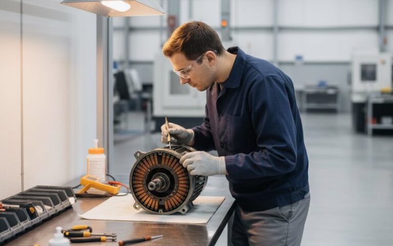
Third, maintenance practices matter more than on cage induction machines. Brush pressure, commutator surface condition, and cooling path cleanliness directly affect commutation and thus torque pulsations, noise, and life. A commutator motor that is theoretically capable of high performance can behave erratically if the brush gear is neglected. That is another reason many engineers prefer to replace them rather than educate a new maintenance team.
Finally, documentation quality is often poor. Many older motors carry only generic markings such as “AC series” or “repulsion motor” without clear indication of whether they are compensated, what brush grade they expect, or how neutral was originally set. Reverse-engineering such machines is more of an investigative task than a design exercise. Having a clear mental picture of the families and their behaviour helps you infer what you are looking at from a few simple tests: torque at start, response to brush shift, and current at rated voltage.
Summary
AC commutator motors form a compact but varied group: series and universal motors dominating low-power tools, repulsion-based machines providing high starting torque in older single-phase drives, shunt and three-phase commutator motors such as the Schrage covering the historic need for variable-speed industrial drives. Their common thread is mechanical commutation on an AC supply, with all the benefits and penalties that brings. Understanding which type you have, and what that implies for torque, control, power quality, and maintenance, is still useful even in a world that now defaults to induction motors and electronic drives.